

Plots allow you to display curves and images in Kst. The Edit Plot dialog is used to change a plot's content, appearance, axes, and markers. To access it, right click on a plot and select the menu item from the context menu, or use the View Manager. There are several tabs:
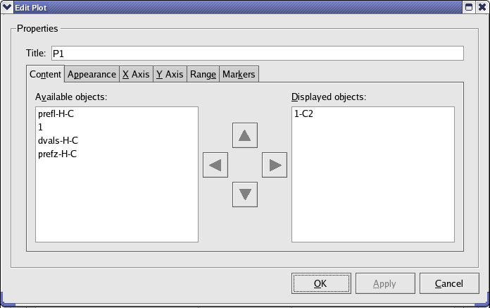
This tab allows you to select which of the available plot objects (curves, images, etc.) will be displayed in the plot. Move objects between the Available and Displayed object lists using the left and right arrow buttons. Change the order in which the objects are plotted with the up and down arrow buttons.
This tab allows you to adjust the colors, fonts, legend, and labels of a plot.
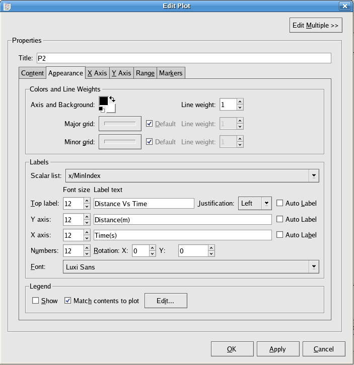
The colors for the axes (foreground) and background of the plot.
The line width in pixels.
The line width and colour of the lines marking out the major/minor grid lines. To enable these grid lines for the axes, use the X Axis/Y Axis tabs.
A list of the current scalars defined in Kst. This list is used to quickly insert values in the label texts. Choosing an item from this list will insert the item at the current text cursor position.
The label located at the top of the plot. Select a font size and enter the text for the label using the controls in this row. These labels can use all of the formatting options of “true” label objects.
This drop-box controls whether the top label will be located at the Left, Right, or Center of the plot's title space. The justification for the X and Y axis labels of a plot is always the center.
The label located vertically next to the X/Y axis of the plot. Select a font size and enter the text for the label using the controls in this row. These labels can use all of the formatting options of “true” label objects.
The numbers used to label both the X axis and the Y axis of the plot. The size and angles of the numbers can be specified. Positive angles rotate the text clockwise, while negative angles rotate the text counter-clockwise.
Click this button to automatically generate label texts for all labels on the plot. The text for Top label will be a list of paths to the data files used in the plot. The text for Y axis will be a list of the dependent variable descriptions (e.g. “Number in Bin” for a histogram). The text for X axis will be the name of the vector used as the independent variable.
The font used for all labels of the plot. Select an available font using the drop-down list.
Check this box if you would like the plot to display a legend.
Check this box if you would like the plot to automatically adjust its legend to reflect its contents.
This button displays the Edit Legend dialog, shown below.
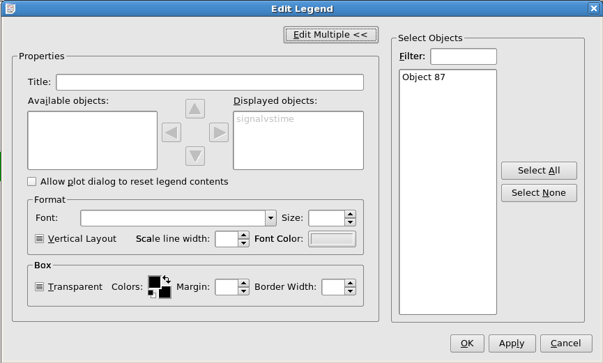
The available options are:
The text for the top of the legend.
This allows you to choose a set of objects to display in the legend which differs from the ones displayed on the plot.
If Match Contents to Plot was not selected in the Edit Plot Dialog, and this option is selected, then the Plot can enforce that its legend matches its true contents.
The formatting options for the legend text.
The properties of the legend outline and fill.
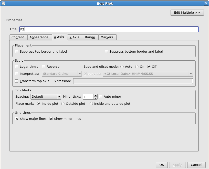
Check this box to remove the white space at the top/bottom of the plot.
Enable this checkbox if you wish to use a logarithmic scale for the axis.
Enabling this option causes the axis to be labelled by displacements from an initial position, where the initial position is displayed in the lower left of the plot. The displacement labels are printed inside square brackets to avoid confusion.
Causes the axis direction to be reversed.
If your axis contains date/time information encoded in a difficult to read form (e.g. Julian Date), this option allows you to have Kst automatically convert it to something more legible. Note: The time data has to be in one of the formats listed in Table 4.1.
Table 4.1. Date Format in Kst
| Date Format | Description | Online Reference |
| Julian Year | a time interval of exactly 365.25 days in astronomy | See definition in wikipedia |
| Standard C time | The amount of time that has elapsed since midnight at the beginning of January 1st 1970 | |
| JD | Julian Date | See definition for Julian Date |
| MJD | Modified Julian Day: the number of days that have elapsed since midnight at the beginning of Wednesday November 17th 1858 | See more details in wikipedia |
| RJD | Reduced Julian Day | See the details in wikipedia |
| TAI | Temps Atomique International (International Atomic Time) | For more details, see this webpage. |
| KDE Short Date and Time | It has the following format: YYYY-MM-DD HH:MM:SS[seconds]. e.g. 1958-01-29 10:05:58[seconds] | |
| KDE Long Date and Time | It has the following format: day date Month Year HH:MM:SS[seconds]. e.g. Wednesday 29 January 1958 10:05:58[seconds] |
Checking this box causes the top axis of the plot to be labelled following the contents of the expression field. The variable x can be used in the expression field to refer to the value on the lower X axis. To plot the top axis as the lower axis scaled by a factor of 2, for example, enter 2*x in the expression field.
Select Course, Default, Fine, or Very Fine from this drop down menu to determine which algorithm Kst will use to determine the number of Major and Minor tick marks which will be plotted.
Unchecking Auto Minor allows you to tell Kst how many minor ticks to place between each pair of major ticks. The number of major ticks cannot be set manually.
Select Inside plot, Outside plot, or Inside and outside plot to determine the location of the tick marks with respect to the axes.
Select these boxes if you would like lines to be drawn through the plot connecting the major/minor tick marks on opposing axes.
The settings for the plot axes are specified on this tab. The axis settings are split into two identical sections — an X axis section and a Y axis section.
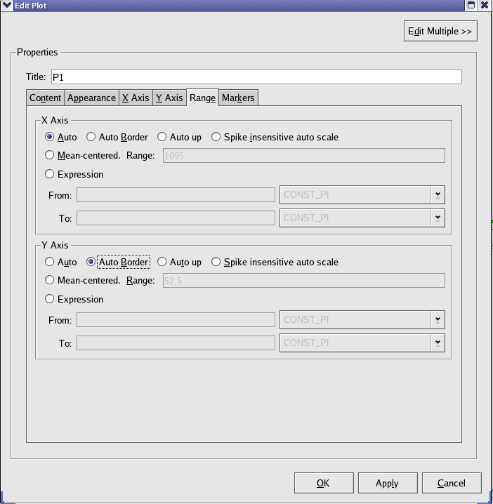
Select this option to let Kst automatically choose a scale for this axis based on the highest and lowest values for this axis found in the plotted objects.
This option behaves similarly to Auto, but the axis is padded with a small amount of extra space. This can sometimes improve the appearance of plots, and make it easier to see features near the range limits.
This option behaves similarly to Auto, but the upper axis limit will only increase, and the lower axis limit will only decrease.
Select this option to let Kst automatically choose a scale for this axis that is based on the values found in the plotted objects. In general, “spikes”, or sudden short increases or decreases in the value, will be ignored when determining the scale. This option is usually for the dependent (Y) axis.
Select this option to center the axis around the mean of the values found in the plot (X values are used to calculate the mean for the X axis, and Y values are used to calculate the mean for the Y axis). Specify the length of the axis in the Range text box.
Manually specify lower and upper limits for the axis. Enter the expression for the limits in the From: and To: textboxes. These can be numerical values, or equations based on the scalars maintained by Kst. These scalars can be quickly added to the expressions by selecting them from the pull-down menus to the right of the textboxes.
Below is a screenshot of the Markers tab.
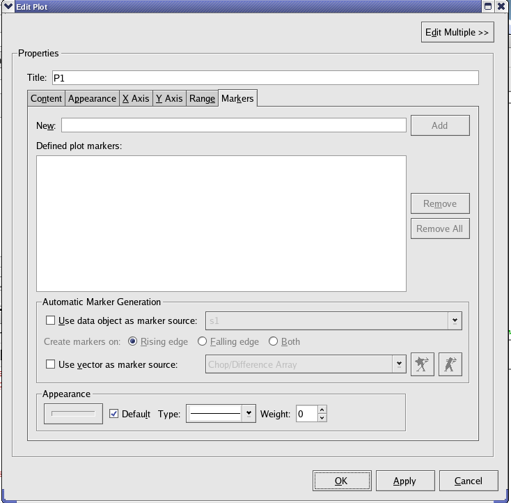
Plot markers provide an easy means of flagging areas of interest on a plot. The Markers tab provides full access to plot marker settings and options. Navigation functions for plot markers are described in the Scroll Menu section.
To quickly create plot markers on a plot, place the mouse cursor over the plot and press the Insert key. A vertical line should appear indicating the position of the plot marker.
Use the New text field to manually enter a plot marker value. Values can be
entered in floating point or scientific notation. Values in scientific notation must be entered in
the form mEx or mex, where m is the
mantissa and x is the exponent. For example, one way to enter the value 15000 in scientific
notation is by typing 1.5e4.
Click the Add button to create a new plot marker with the specified value. You will be warned if duplicate plot markers already exist, or if the entered value is not valid. Note that plot marker additions or removals made from the Markers tab are not applied unless the plot dialog settings are applied.
The list of existing plot markers for this plot are listed under Defined plot markers. To remove plot markers, highlight the desired markers in the list and click the button. Multiple markers can be selected for removal by clicking and dragging within the list, or by holding down the Shift or Ctrl key and clicking on items in the list. To remove all plot markers for this plot, click the Remove All button. Note that plot marker additions or removals made from the Markers tab are not applied unless the plot dialog settings are applied.
In addition to individually defined plot markers, it is also possible to generate plot markers based on a curve. To use a curve object for plot marker generation, check the Use data object as marker source checkbox and select a curve from the drop down list. Then select the criteria for creating plot markers. Selecting Rising edge causes plot markers to be created when the Y value of the selected curve changes from zero to non-zero. Selecting Falling edge causes plot markers to be created when the Y value of the selected data object changes from non-zero to zero. Selecting Both causes plot markers to be created on both rising edges and falling edges of the data object. In all cases, the X value of the point in the data object with the non-zero X value is used to create the new plot marker.
If the selected curve is subsequently updated, additional plot markers will be created if necessary. However, plot markers will never be removed as a consequence of data object changes, so manually created plot markers will never be affected.
It is also possible to create plot markers from a vector. Enable the Use vector as marker source checkbox and select a data vector from the drop down menu. The values of this vector will now be used as markers
These options allow you to select the colour, line type, and weight (thickness) of the plot markers.
Plots in Kst can also be manipulated by KstScript. You can change the view of a plot by modifying its properties defined in the Plot Class, such as legend, topLabel, x/yAxis, etc.
See the Plot Class of the Script Chapter for detail. In order to change the view of a plot, you often need to use the Plot Class with other classes, such as the Axis Class, or the Curve Class.
The example below is to show how to use the Plot Class and the TimeInterpretation Class to interpret various date formats for a plot.
Example 4.1. Example of Using the Plot Class to interpret date format for x Axis
w = new Window(); 		//construct a new window
p = new Plot(w);            	// place a plot on the window
c = new Curve("time","Y"); 	// use vector “time” and “Y” to construct a new curve
c.tagName = "time vs Y";
p.curves.append(c); 		   	//to show the curve on the plot
p.xAxis.interpretation.input = 2; 	// the input “time” vector is in Julian Date.
				 	 //2 stands for Julian Date in the TimeInterpretation Class.
p.xAxis.interpretation.output = 0; 	//  the “time” vector needs to be shown in
				   	//the format: DD/MM/YY HH:MM:SS.

p.xAxis.interpretation.active = true; 	//Active the interpretation
Annotation objects are Labels, Boxes, Ellipses, Lines, Arrows and Pictures. They can be easily created by choosing the in the menu.
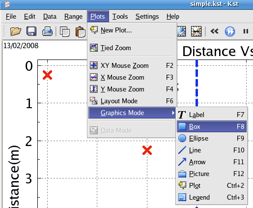
To edit an annotation object, right click on the object and choose the menu item in the context menu.
To move or resize an annotation object, you must be in Layout mode.
Custom labels can be displayed in arbitrary locations in Kst plot windows.
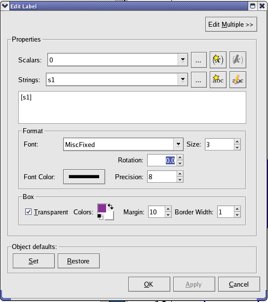
The following are explanations of the dialog box elements.
A list of scalars currently defined in Kst. Selecting an item from the dropdown list inserts a reference to the scalar's value at the current cursor position in the label text.
A list of strings currently defined in Kst. Selecting an item from the dropdown list inserts a reference to the string's contents at the current cursor position in the label text.
The text displayed by the label. You may enter text manually in this dialog, or insert references into it using the scalar and string drop down menus. Kst labels support many LaTeX formatting and symbol commands, prefixed with the usual “\”. A list of supported commands is given in the table below:
Table 4.2. LaTeX Commands Supported in Label Text
| Command | Result | |
|---|---|---|
| \Greeklettername |  | Uppercase Greek letters. E.g. \Gamma. |
| \greeklettername |   | Lowercase Greek letters. E.g. \gamma, \delta. |
| \approx |  | Approximately equal to. |
| \cdot |  | Center dot- dot product. |
| \geq, \ge |  | Greater than or equal to. |
| \leq, \le |  | Greater than or equal to. |
| \t | Tab space. | |
| \n | Newline. | |
| \partial |  | Partial difference. |
| \sqrt |  | Square root. |
| \inf |  | Infinity. |
| \int |  | Integral. |
| \pm |  | Plus-minus sign. |
| \[, \] |  | Square-brackets. |
| \sum |  | Summation sign. |
| \prod |  | N-ary product. |
| y^{x} |  | Write x as superscript. |
| y_{x} |  | Write x as subscript. |
| \textit{'text'} |  | Write 'text' in italics. |
| \textbf{'text'} |  | Write 'text' in bold font. |
| \underline{'text'} |  | Write 'text' with underline. |
| \textcolor{'color'}{'text'} |  | Write 'text' in 'color'. |
The font to use for the label text. Select a font from the dropdown list.
The size of the label text. 0 (the default value) roughly corresponds to a 12pt size.
The number of degrees to rotate the label text. Positive values rotate the label clockwise, while negative values rotate the text counter-clockwise.
Select the color to use for the label text. Clicking the  button displays
the standard KDE color chooser.
When scalar variables are included in labels, Precision dictates the number of digits which are displayed.
Select the color to use for the label text. Clicking the  button displays
the standard KDE color chooser.
Once you are satisfied with the label settings, click the button to view the label settings without closing the Edit Label dialog. Click the button to apply the label settings and close the dialog. Alternatively, you can click the button to close the Edit Label dialog without applying any label settings.
Box and ellipse annotation objects are usually used to outline important features on a plot.
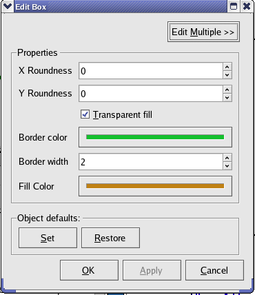
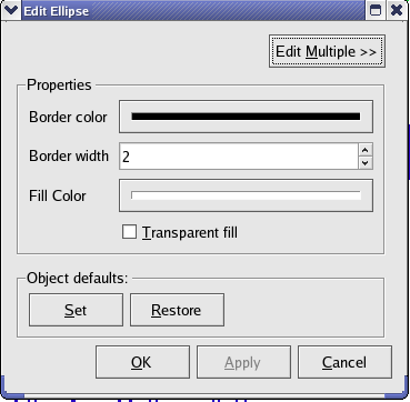
The following are explanations of the dialog box elements.
The color of the outline of the box/ellipse object. Clicking the  button displays the standard KDE color chooser.
The width of the annotation's line/border (in pixels).
The color of the contents of the box/ellipse. Clicking the  button displays the standard KDE color chooser. If you select Transparent Fill then the box/ellipse will be see-through.
These options are for boxes only. They determine the fractional rounding of the box's corners. Values of 0 result in standard corners (right angles), while values of 99 result in a maximally rounded box (an ellipse). For more information on these options, see the Qt documentation on QPainter::drawRoundRect.
Line and Arrow annotation objects are usually used to highlight important features on a plot (by pointing to a particular peak, for example.).
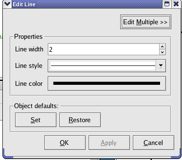
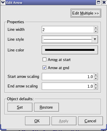
The following are explanations of the dialog box elements.
The color of the line/arrow object. Clicking the  button displays the standard KDE color chooser.
Here you can chose to make the line solid, dashed, dot-dashed, etc.
The width of the line (in pixels). This will also change the head size for an arrow object.
Determines where to place the arrow heads. The heads will always point away from the line.
A scaling factor for the arrow head sizes. This can be useful if your line width leads to a head size which is larger than you would like.
Picture objects can be used to easily add an external graphic to your plot. More popular image formats are supported, depending on the libraries installed on your system.
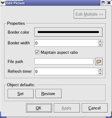
The following are explanations of the dialog box elements.
The color of the outline of the box/ellipse object. Clicking the  button displays the standard KDE color chooser.
The width of the annotation's line/border (in pixels).
If this box is checked, then when resizing the picture object Kst will maintain the ratio between the width and height of the picture. You can temporarily disable (or enable) this option by holding down the Shift key as you resize the picture.
The location of the image you would like to display.
Set this to the period (in seconds) with which you would like Kst to check the image file for updates, and reload it if necessary. If the refresh timer is set to 0 then the image will only be reloaded after restarting Kst or opening and closing the picture object's edit dialog.
You can construct and edit annotation objects from the corresponding classes in KstScript. See details in
To change a general property of an annotation object, such as moving or resizing an object, you may use methods and properties defined in the ViewObject Class, the super class of all annotation objects.
Example 4.2. Function for Creating and Resizing Annotation Objects
If you use the code below to create an annotation object, for example, a box, in tab W1:
b = new Box("W1");
You may notice that there is nothing in W1. However, the new box is actually created. It has a very small size and is sitting in the position (0,0), the upper left corner of the Kst window; therefore, it is necessary to move and resize it in order to make it visible. Notice that you will need to change the default settings for every annotation object you create, so it may be more convenient to use a KstScript function to do that. The following is an example function which will create a user specified annotation object, and then resize and move this object to the position (250,250) on the user specified window.
//annotation.js
//A(string) is the name of an annotation object
//W(string) is the name of a window
function createAnot(A, W)
{
//declare strings to hold names of possible annotation objects
lb = new String();
lb.value = "Label";
b  = new String();
b.value = "Box";
e = new String();
e.value = "Ellipse";
l = new String();
l.value = "Line";
a = new String();
a.value = "Arrow";
input = new String();//declare a string to hold the name of the user specified annotation object
input.value = A;
//create the user specified annotation object and resize it to let it become visible
if(input.value==lb.value)
{
anot = new Label(W);
anot.tagName = "new Label";
anot.resize(new Size(100,100));
anot.text = "Enter Text Here";
}
else if(input.value==b.value)
{
anot = new Box(W);
anot.tagName = "new Box";
anot.resize(new Size(100,100));
}
else if(input.value==e.value)
{
anot = new Ellipse(W);
anot.tagName = "new Ellipse";
anot.resize(new Size(100,100));
}
else if(input.value==l.value)
{
anot = new Line(W);
anot.tagName = "new Line";
anot.to = new Point(100,100);
anot.width = 2;
}
else
{
anot = new Arrow(W);
anot.tagName = "new Arrow";
anot.toArrow = true;
anot.to= new Point(100,100);
}
//move this annotation object to the position (250,250)
anot.move(new Point(250,250));
 }
After loading this function script in Kst, you can create an edited annotation object like this:
createAnot("Label","W1");
Would you like to make a comment or contribute an update to this page?
Send feedback to the KDE Docs Team